Zephyr设备树生成C宏规则
本文说明Zephyr下设备树生成C宏的规则。
从Zephyr设备树生成流程一文中知道, 设备树作为C宏被Zephyr引用,C宏是gen_defines.py搭配yaml文件解析dts生成。涉及到dts转化为C宏的所有python脚本文件都在zephyr/scripts/dts下,分别为 dtlib.py 底层的dts解析 edtlib.py 位于dtlib之上,用来解释绑定属性,使用dtlib解析dts gen_defines.py 使用edtlib.py生成C宏 分析这些脚本虽然可以让我们深入了解DTS转换成宏的流程,但对于我们一般使用Zephyr DTS并无太大必要,本文不分析这些脚本,只说明Zephyr使用什么规则将dts转化为C宏(这也主要是edtlib.py 的工作内容),以此帮助我们在分析Zephyr驱动时知道一些宏的来源,同时当了解这些规则也会对分析宏生成脚本有帮助。
概述 链接到标题
dts文件用来描述硬件信息,但构建系统并不知道dts内那些信息对设备驱动有用,也就无法知道dts那些内容会被生成宏。于是Zephyr提供了bindings文件yaml,该文件告诉构建系统那些dts内的信息会被转换成宏。在构建阶段使用gen_defines.py会尝试把dts内每个节点和yaml文件内容匹配,只为能匹配上的dts节点生成宏。阅读本文需要了解dts的基本概念和binding,dts的基本概念网上有很多,这里就不做介绍也可以参考文末zephyr dts的介绍链接. Binding下面会简单介绍,已方便之后理解如何生成宏。
Devicetree bindings 链接到标题
Devicetree的binding文件放在zephyr/dts/bindings, 用于告诉gen_defines.py dts中那些信息要被生成宏和以什么样的形式生成宏。在构建阶段使用gen_defines.py会尝试把dts内每个节点和yaml文件内容匹配,只为能匹配上的dts节点生成宏。
匹配方式 链接到标题
dts通过note内的compatible 属性指和yaml文件名进行匹配,例如:
	sdram0: memory@80000000 {
		/* Micron MT48LC16M16A2B4-6AIT:G */
		device_type = "memory";
		compatible = "mmio-sram";
		reg = <0x80000000 0x2000000>;
	};
上面这个节点的compatible的值是"mmio-sarm",那么它就会去dts/bindings中去找mmio-sarm.yaml文件来绑定,如下
description: Generic on-chip SRAM description

compatible: "mmio-sram"

include: base.yaml

properties:
    reg:
      required: true

    label:
      required: false
node可以指定多个compatible,从前到后依次匹配,先匹配到那个就用那个,例如
is25wp064: is25wp064@0 {
				compatible = "issi,is25wp064", "jedec,spi-nor";
				size = < 0x4000000 >;
				label = "IS25WP064";
				reg = < 0x0 >;
				spi-max-frequency = < 0x7ed6b40 >;
				status = "okay";
				jedec-id = [ 9D 70 17 ];
			};
如果找到了issi,is25wp064.yaml就直接用,没找到就继续找jedec,spi-nor.yaml
节点如果没有指定compatible,则使用父节点的compatible,例如下例中red_pwm_led和green_pwm_led都是匹配的pwm-leds.yaml
pwmleds {
        compatible = "pwm-leds";

        red_pwm_led {
                pwms = <&pwm3 4 15625000>;
        };
        green_pwm_led {
                pwms = <&pwm3 0 15625000>;
        };
        ...
};
如果节点描述了总线上的硬件(例如I2C或SPI),则在将节点映射到绑定时要考虑总线类型。 在查找节点的绑定时,要检查父节点的绑定是否包含***bus: <bus type>***和只会绑定和父节点bus type匹配的节点。例如
&i2c0 {
	compatible = "nordic,nrf-twi";
	status = "okay";
	sda-pin = <5>;
	scl-pin = <4>;
	clock-frequency = <I2C_BITRATE_FAST>;

	ssd1306@3c{
		compatible = "solomon,ssd1306fb";
		reg = <0x3c>;
		label = "SSD1306";
		width = <128>;
		height = <64>;
		multiplex-ratio = <63>;
		segment-offset = <0>;
		page-offset = <0>;
		display-offset = <0>;
		segment-remap;
		com-invdir;
		prechargep = <0x22>;
	};
ssd1306@3c绑定的是solomon,ssd1306fb.yaml,当中会include到i2c-device.yaml
on-bus: i2c

properties:
    reg:
      required: true
    label:
      required: true
其父节点i2c0绑定的是nordic,nrf-twi.yaml,当中互include到i2c-controller.yaml
bus: i2c

properties:
    "#address-cells":
      required: true
      const: 1
    "#size-cells":
      required: true
      const: 0
    clock-frequency :
      type: int
      required: false
      description: Initial clock frequency in Hz
    label:
      required: true
可以看到父节点绑定描述了bus是i2c,子节点绑定描述on-bus是i2c,二者匹配才会继续生成宏。
绑定文件语法 链接到标题
本文主旨不是说明绑定文件语法,详细可以参考源代码中dts/binding-template.yaml 在2.1以前的zephyr和当前zephyr 2.2.99的绑定语法不一样, 当前zephyr还同时支援两种语法,但2.3后将废弃2.1老的绑定语法。
宏生成 链接到标题
由dts产生的宏都是以DT_开头,全部为大写, C宏基本都是dts的属性,例如
#define DT_NXP_IMX_FLEXSPI_402A8000_JEDEC_SPI_NOR_0_JEDEC_ID {0x9d, 0x70, 0x17}
说明了一个SPI Flash上的jedec id是多少,接下来我们来宏名字和对应的值是怎么生成的。
节点C标识 链接到标题
宏的C标识是由节点或者节点属性以DT_<node>的形式生成,这里以MadMachine SwiftIO中spi flash,led,pwm的dts实例说明不同节点C标识<node>的生成规则
在mm_swiftio.dts中有如下片段
aliases {
	led1 = &red_led;
};

leds {
	compatible = "gpio-leds";
	red_led: led_0 {
		gpios = <&gpio1 9 0>;
		label = "RGB R";
	};
};

&flexspi0 {
	reg = <0x402a8000 0x4000>, <0x60000000 0x800000>;
	is25wp064: is25wp064@0 {
		compatible = "issi,is25wp064", "jedec,spi-nor";
		size = <67108864>;
		label = "IS25WP064";
		reg = <0>;
		spi-max-frequency = <133000000>;
		status = "okay";
		jedec-id = [9d 70 17];
	};
};
被预编译后展开为(zephyr.dts), 对于led没有父节点所以没有变化,spi flash被展开, pwm是mm_swiftio.dts中include的dtsi带有的
aliases {
	led1 = &red_led;
}

leds {
	compatible = "gpio-leds";
	red_led: led_0 {
		gpios = <&gpio1 9 0>;
		label = "RGB R";
	};
};

flexspi0: spi@402a8000 {
	compatible = "nxp,imx-flexspi";
	reg = < 0x402a8000 0x4000 >, < 0x60000000 0x800000 >;
	interrupts = < 0x6c 0x0 >;
	label = "FLEXSPI0";
	#address-cells = < 0x1 >;
	#size-cells = < 0x0 >;
	is25wp064: is25wp064@0 {
		compatible = "issi,is25wp064", "jedec,spi-nor";
		size = < 0x4000000 >;
		label = "IS25WP064";
		reg = < 0x0 >;
		spi-max-frequency = < 0x7ed6b40 >;
		status = "okay";
		jedec-id = [ 9D 70 17 ];
	};
};

flexpwm1: flexpwm@403dc000 {
	compatible = "nxp,flexpwm";
	reg = < 0x403dc000 0x4000 >;
	interrupts = < 0x6a 0x0 >;
	flexpwm1_pwm0: pwm0 {
		compatible = "nxp,imx-pwm";
		index = < 0x0 >;
		label = "FLEXPWM1_PWM0";
		interrupts = < 0x66 0x0 >;
		#pwm-cells = < 0x1 >;
	};
	flexpwm1_pwm1: pwm1 {
		compatible = "nxp,imx-pwm";
		index = < 0x1 >;
		label = "FLEXPWM1_PWM1";
		interrupts = < 0x67 0x0 >;
		#pwm-cells = < 0x1 >;
	};
};
要生成的节点C标识有下面3种
1. DT_(<bus>_)<compatible>_<unit-address>转换规则 链接到标题
对于每个节点来说通常都满足DT_(<bus>_ )<compatible>_<unit-address>,也就是节点的兼容属性转换为C标识符,后跟其单元地址, 例如spi@402a8000的C标识就是DT_NXP_IMX_FLEXSPI_402A8000
- 该节点没有bus
- 兼容属性compatible为"nxp,imx-flexspi", 将字母数字转换为大写,其它符号转换为下划线得到NXP_IMX_FLEXSPI
- 单元地址402a8000,转换为大写402A8000
如果有bus就需要加入bus,如果兼容属性有多个,使用首个匹配的兼容属性 例如is25wp064@0的C标识符是DT_NXP_IMX_FLEXSPI_402A8000_JEDEC_SPI_NOR_0
- 该节点的bus是其父节点spi@402a8000,因此bus使用NXP_IMX_FLEXSPI_402A8000
- 兼容属性compatible为"jedec,spi-nor", 转换为JEDEC_SPI_NOR
- 单元地址0,转换为大写0
兼容属性的确认: is25wp064@0 先找issi,is25wp064.yaml找不到,然后使用"jedec,spi-nor.yaml"
bus的确认: 在"jedec,spi-nor.yaml"中有
include: [spi-device.yaml, "jedec,spi-nor-common.yaml"]
里面使用了spi-device.yaml,其中包含
on-bus: spi
因此可知道is25wp064@0是在spi bus上。 再解析其父节点的nxp,imx-flexspi.yaml当包含了spi-controller.yaml
include: spi-controller.yaml
spi-controller.yaml中有
bus: spi
因此可以将子节点的spi bus和父节点bus对上,而确认bus使用NXP_IMX_FLEXSPI_402A8000。
如果节点没有单元地址,则将父节点的单元地址加上转换为C标识符的节点名称用于<unit-address> 例如pwm0的C标识符是DT_NXP_IMX_PWM_403DC000_PWM0
- 该节点没有bus
- 兼容属性是nxp,imx-pwm,转换为NXP_IMX_PWM
- 该节点没有地址,使用父节点地址403dc000和自己的节点名pwm0,转为<unit-address> 是403DC000_PWM0
如果父节点也没有单元地址,则将直接使用该节点的名称 例如led_0的C标识符是DT_GPIO_LEDS_LED_0
- 该节点没有bus
- 该节点没有兼容属性,就使用父节点的兼容属性gpio-leds, 转换为GPIO_LEDS
- 该节点和父节点都没有单元地址,使用该节点名led_0做为<unit-address> , 转换为LED_0
2. DT_INST_<instance-number>_ <compatible>转换规则 链接到标题
节点兼容属性实例编号,对某个兼容属性进行实例编号,对整个dts中有相同兼容属性且被enable的节点(status = “okay”)进行编号,转换方法就是DT_INST搭配实例号和兼容属性 例如"jedec,spi-nor"转换出来就是DT_INST_0_JEDEC_SPI_NOR
- “jedec,spi-nor"兼容属性只出现了一次,因此只会有一个0编号的JEDEC_SPI_NOR 例如"nxp,imx-pwm"出现了2次并都被enable,就会有2个实例,依次为DT_INST_0_NXP_IMX_PWM和DT_INST_1_NXP_IMX_PWM
3. DT_ALIAS_<alias> 链接到标题
别名生成,对于led1别名,生成后DT_ALIAS_LED1,<alias>转换规则就是别名字母数字转换为大写,其它符号转换为下划线
节点属性宏生成 链接到标题
节点属性宏以DT_<node>_<property>形式转换,上一节已经说明了<node>如何生成,这节再说明属性的转换就可以完成从dts到宏的转换了。 属性转换可以分为2种,一种是通用的,一种是指定关键字的。
通用转换规则 链接到标题
通用的是指非特定的关键字,都以一种通用的规则进行转换,转换规则如下
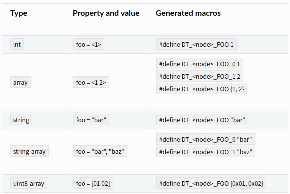
对于boolean类型,如果节点存在该属性者值为1,否则为0
#define DT_<node>_FOO 0/1
对于非boolean类型,如果绑定yaml文件中类别是optional并且该属性不在dts中,则不会生成属性宏。 另外还有phandle-array和enum类型,phandle-array后文结合clock介绍。
以is25wp064@0的jedec-id = [ 9D 70 17 ];举例,属于uint8-array类型 <node> 前文已说过如何转为NXP_IMX_FLEXSPI_402A8000_JEDEC_SPI_NOR_0 <property>是jedec-id,转为JEDEC_ID 按照uint8-array进行进行转换因此最后会得到
#define DT_NXP_IMX_FLEXSPI_402A8000_JEDEC_SPI_NOR_0_JEDEC_ID {0x9d, 0x70, 0x17}
特殊关键字转换规则 链接到标题
在dts中用得最多的就是特殊关键字,这里一一说明 reg属性 reg会被转换成一组地址和大小的宏:DT_<node>BASE_ADDRESS(_<index>) 和 DT<node>_SIZE( _<index>). 当只有一个寄存器时没有index 例如flexpwm@403dc000的reg = < 0x403dc000 0x4000 >;会被转换为
#define DT_NXP_FLEXPWM_403DC000_BASE_ADDRESS        0x403dc000
#define DT_NXP_FLEXPWM_403DC000_SIZE                16384
index是在有多个寄存器是才有,被当做索引例如 例如spi@402a8000的 < 0x402a8000 0x4000 >, < 0x60000000 0x800000 >会被转换为
#define DT_NXP_IMX_FLEXSPI_402A8000_BASE_ADDRESS_0  0x402a8000
#define DT_NXP_IMX_FLEXSPI_402A8000_SIZE_0          16384
#define DT_NXP_IMX_FLEXSPI_402A8000_BASE_ADDRESS_1  0x60000000
#define DT_NXP_IMX_FLEXSPI_402A8000_SIZE_1          8388608
interrupts属性 中断生成规则为DT_<node>_IRQ_<index>(_ <name>)和DT_<node>_IRQ_<index>(_<name>)_PRIORITY , node就是前面的C标识符,index是中断顺序编号,当有属性指定中断名时才会有<name> 以spi@402a8000的interrupts = < 0x6c 0x0 >为例,0x6c是IRQ号,0是中断优先级,将会生成
#define DT_NXP_IMX_FLEXSPI_402A8000_IRQ_0           108
#define DT_NXP_IMX_FLEXSPI_402A8000_IRQ_0_PRIORITY  0
多中断和带中断名的示例
timer@456 {
    interrupts = <10 50 20 60>;
    interrupt-parent = <&intc>;
    interrupt-names = "timer-a", "timer-b";
    /* ... */
};
产生宏
#define DT_<node>_IRQ_TIMER_A             1
#define DT_<node>_IRQ_TIMER_A_PRIORITY    5
#define DT_<node>_IRQ_TIMER_B             2
#define DT_<node>_IRQ_TIMER_B_PRIORITY    6
clocks属性 clocks是phandle-array类型,前文没有介绍这里合并一起分析。phandle-array可以认为是引用了其它节点的类型,如下uart中的clocks
		ccm: ccm@400fc000 {
			compatible = "nxp,imx-ccm";
			reg = < 0x400fc000 0x4000 >;
			label = "CCM";
			#clock-cells = < 0x3 >;
			phandle = < 0x2 >;
		};

		uart1: uart@40184000 {
			compatible = "nxp,kinetis-lpuart";
			reg = < 0x40184000 0x4000 >;
			interrupts = < 0x14 0x0 >;
			clocks = < &ccm 0x3 0x7c 0x18 >;
			label = "UART_1";
			status = "okay";
			current-speed = < 0x1c200 >;
		};
在nxp,imx-ccm.yaml中可以找到clock-cells的声明如下
clock-cells:
  - name
  - offset
  - bits
可以生成下面的宏DT_<node>CLOCK_CONTROLLER(<index>), DT_<node>CLOCK_NAME<index>, DT_<node>CLOCK_OFFSET<index>,DT_<node>CLOCK_BITS<index> 它们对应的值要从clocks = < &ccm 0x3 0x7c 0x18 >;中取 CONTROLLER就是ccm节点的lable,其它的就是clocks中一次定义,转化为宏如下
#define DT_NXP_KINETIS_LPUART_40184000_CLOCK_CONTROLLER "CCM"
#define DT_NXP_KINETIS_LPUART_40184000_CLOCK_NAME_0 3
#define DT_NXP_KINETIS_LPUART_40184000_CLOCK_OFFSET_0 124
#define DT_NXP_KINETIS_LPUART_40184000_CLOCK_BITS_0 24
如果clocks的controller节点有fixed-clock的兼容属性, 那么该节点必须有一个clock-frequency属性,值就是HZ,该节点将会生成附加宏DT_<node>_CLOCKS_CLOCK_FREQUENCY例如
	sysclk: system-clock {
		compatible = "fixed-clock";
		clock-frequency = < 0x23c34600 >;
		#clock-cells = < 0x0 >;
		phandle = < 0x3 >;
	};
会生成
#define DT_FIXED_CLOCK_SYSTEM_CLOCK_CLOCK_FREQUENCY 600000000
cs-gpios属性 该属性是提供给bus的片选用 ,例如芯片有spi总线,当一条总线上挂有多个spi device,device node就需要使用该属性,目前mm_swiftio上没有总线上挂多个设备的情况,这里以官网上的一个例子说明
gpioa: gpio@400ff000 {
     compatible = "vendor,gpio-ctlr";
     reg = <0x400ff000 0x40>;
     label = "GPIOA";
     gpio-controller;
     #gpio-cells = <1>;
};

spi {
     compatible = "vendor,spi-controller";
     spi-slave@0 {
             compatible = "vendor,foo-spi-device";
             reg = <0>;
             cs-gpios = <&gpioa 1>;
     };
     spi-slave@1 {
             compatible = "vendor,bar-spi-device";
             reg = <1>;
             cs-gpios = <&gpioa 2>;
     };
};
上面dts表达的意思是spi总线上挂有spi-slave设备0和1,分别使用gpioa 1和gpioa 2作为片选,可以看出cs-gpios也是phandle-array,这里生成宏将是
#define DT_<node>_CS_GPIOS_CONTROLLER    "GPIOA"
#define DT_<node>_CS_GPIOS_PIN           1
#define DT_<node>_CS_GPIOS_PIN           2
其它宏 链接到标题
本节介绍为属性产生附加宏
节点存在标识 链接到标题
节点存在标识用于标识设备树中包含那些节点匹配条件 存在某个兼容属性 使用#define DT_COMPAT_<compatible> 1,例如有节点使用compatible = “nxp,imx-flexspi"就会有
#define DT_COMPAT_NXP_IMX_FLEXSPI 1
总线相关的宏 链接到标题
某个节点如果出现在总线上会附加出现该宏,形式如下
#define DT_<node>_BUS_NAME                "<bus-label>"
#define DT_<compatible>_BUS_<bus-name>    1
<bus-lable> 是该bus节点的lable,<bus-name>是该节点绑定属性的的on-bus。 例如is25wp064: is25wp064@0对应产生的宏就是
#define DT_NXP_IMX_FLEXSPI_402A8000_JEDEC_SPI_NOR_0_BUS_NAME "FLEXSPI0"
#define DT_INST_0_JEDEC_SPI_NOR_BUS_NAME            DT_NXP_IMX_FLEXSPI_402A8000_JEDEC_SPI_NOR_0_BUS_NAME
#define DT_JEDEC_SPI_NOR_BUS_SPI                    1
Flash分区的宏 链接到标题
如果节点名的形式是partition@<unit-address>, 这将作为一个flash分区进行解析,例如下面DTS
flash@0 {
     /* ... */
     label = "foo-flash";

     partitions {
             /* ... */
             #address-cells = <1>;
             #size-cells = <1>;

             boot_partition: partition@0 {
                     label = "mcuboot";
                     reg = <0x00000000 0x00010000>;
                     read-only;
             };
             slot0_partition: partition@10000 {
                     label = "image-0";
                     reg = <0x00010000 0x00020000
                            0x00040000 0x00010000>;
             };
             /* ... */
};
产生的宏是
#define DT_FLASH_AREA_MCUBOOT_ID           0
#define DT_FLASH_AREA_MCUBOOT_READ_ONLY    1
#define DT_FLASH_AREA_MCUBOOT_OFFSET_0     0x0
#define DT_FLASH_AREA_MCUBOOT_SIZE_0       0x10000
#define DT_FLASH_AREA_MCUBOOT_OFFSET       DT_FLASH_AREA_MCUBOOT_OFFSET_0
#define DT_FLASH_AREA_MCUBOOT_SIZE         DT_FLASH_AREA_MCUBOOT_SIZE_0
#define DT_FLASH_AREA_MCUBOOT_DEV          "foo-flash"

#define DT_FLASH_AREA_IMAGE_0_ID           0
#define DT_FLASH_AREA_IMAGE_0_READ_ONLY    1
#define DT_FLASH_AREA_IMAGE_0_OFFSET_0     0x10000
#define DT_FLASH_AREA_IMAGE_0_SIZE_0       0x20000
#define DT_FLASH_AREA_IMAGE_0_OFFSET_1     0x40000
#define DT_FLASH_AREA_IMAGE_0_SIZE_1       0x10000
#define DT_FLASH_AREA_IMAGE_0_OFFSET       DT_FLASH_AREA_IMAGE_0_OFFSET_0
#define DT_FLASH_AREA_IMAGE_0_SIZE         DT_FLASH_AREA_IMAGE_0_SIZE_0
#define DT_FLASH_AREA_IMAGE_0_DEV          "foo-flash"
* _ID的宏表示分区的索引,从零开始编号。 * _OFFSET_ <index>和* _SIZE_ <index>宏给对应分区节点中reg内的值,表示分区的偏移地址和大小。
宏生成范式 链接到标题
前面说了这么多只是帮助理解,关于dts生成宏zephyr官网提供了扩充巴克斯范式(ABNF)描述转化的语法,有兴趣的朋友可以参考
; dt-macro is the top level nonterminal. It defines the possible
; macros generated by gen_defines.py.
;
; A dt-macro starts with uppercase "DT_" followed by either:
;
; - a property-macro, generated for a particular node
;   property
; - some other-macro, a catch-all for other types of macros,
;   which contain either global information about the tree or
;   are special cases
;
; This does *not* cover macros pulled out of DT via Kconfig,
; like CONFIG_SRAM_BASE_ADDRESS, etc.
dt-macro = %s"DT_" ( property-macro / other-macro )

; --------------------------------------------------------------------
; A property-macro is a sequence of:
;
; - node-id: a way to identify a node
; - property-id: a way to identify one of the node's properties
; - property-suf: an optional property-specific suffix
property-macro    = node-id "_" property-id ["_" property-suf]

; A node-id is a way to refer to a node within the devicetree.
; There are a few different flavors.

node-id           = compat-unit-id / inst-id / alias-id

compat-unit-id    = [bus-id-part "_"] compat-id-part "_" unit-addr-id-part
inst-id           = %s"INST_" 1*DIGIT "_" compat-id-part
alias-id          = %s"ALIAS_" alias-id-part

; Various components of a property-macro are just c-idents,
; which are made of uppercase letters, numbers, and underscores.
;
; This is a problem, because it makes it possible for different nodes
; or properties in a devicetree to generate the same macro twice
; with different values.

bus-id-part       = c-ident     ; ID for information about a node's bus
compat-id-part    = c-ident     ; ID for a node's compatible
unit-addr-id-part = c-ident     ; ID for a node's unit-address
alias-id-part     = c-ident     ; ID for an /aliases node property
property-id       = c-ident     ; ID for a node property -- this also
                                ; covers special cases like "reg",
                                ; "interrupts", and "cs-gpios" for now,
                                ; as they all collide with non-special
                                ; cases.
property-suf      = c-ident     ; a suffix for part of a property value,
                                ; like an array index or a phandle
                                ; specifier name converted to a c-ident

; --------------------------------------------------------------------
; An other-macro is a grab bag for everything that isn't a
; property-macro. It reuses some of the nonterminals (namely node-id
; and compat-id-part) defined above.
other-macro     = existence-flag / bus-macro / flash-macro / chosen-macro

existence-flag  = compat-existence-flag / inst-existence-flag
compat-flag     = %s"COMPAT_" c-ident
inst-flag       = %s"INST_" 1*DIGIT "_" c-ident

bus-macro       = bus-name-macro / on-bus-macro
bus-name-macro  = node-id %s"_BUS_NAME"
on-bus-macro    = compat-id-part %s"_BUS_" bus-name
bus-name        = c-ident       ; a bus name ("i2c") to a DT C
                                ; identifier ("I2C")

flash-macro     = %s"FLASH_AREA_" node-label-ident "_" flash-suf
flash-suf       = %s"ID" / %s"READ_ONLY" / (%s"OFFSET" ["_" 1*DIGIT]) /
                  (%s"SIZE" ["_" 1*DIGIT]) / %s"DEV"

; Macros generated from /chosen node properties.
chosen-macro    = chosen-flash /
                  %s"CODE_PARTITION_OFFSET" / %s"CODE_PARTITION_SIZE" /
                  %s"CCM_BASE_ADDRESS" / %s"CCM_SIZE" /
                  %s"DTCM_BASE_ADDRESS" / %s"DTCM_SIZE" /
                  %s"IPC_SHM_BASE_ADDRESS" / %s"IPC_SHM_SIZE"
; These come from the /chosen/zephyr,flash property.
chosen-flash    = %s"FLASH_BASE_ADDRESS" /
                  %s"FLASH_SIZE" /
                  %s"FLASH_ERASE_BLOCK_SIZE" /
                  %s"FLASH_WRITE_BLOCK_SIZE"

; --------------------------------------------------------------------
; Helper definitions.

; A c-ident is one or more:
; - uppercase letters (A-Z)
; - numbers (0-9)
; - underscores ("_")
;
; They are the result of converting names or combinations of names
; from devicetree to a valid component of a C identifier by
; uppercasing letters and converting non-alphanumeric characters to
; underscores.
c-ident = 1*( UPPER / DIGIT / "_" )

; a node's "label" property value, as an identifier
node-label-ident = c-ident

; "uppercase ASCII letter" turns out to be pretty annoying to specify
; in RFC-7405 syntax.
;
; This is just ASCII letters A (0x41) through Z (0x5A).
UPPER = %x41-5A
参考 链接到标题
https://docs.zephyrproject.org/latest/guides/dts/intro.html https://docs.zephyrproject.org/latest/boards/arm/mm_swiftio/doc/index.html https://docs.zephyrproject.org/latest/guides/dts/macros.html